
Fontana, California · AS9100D · ISO 9001 · ITAR Registered
Tube laser cutting, CNC bending and metal fabrication — under one roof.
Seven departments in one building in Fontana, California. One shop accountable for the whole part.


Six departments. One building. No hand-offs.
CalWest Manufacturing is an AS9100D and ISO 9001 certified, ITAR registered contract manufacturer in Fontana, California. Tube laser cutting, CNC tube bending, plate laser cutting, press brake forming, welding, 5-axis machining and FANUC robotic integration all happen under one roof — so a part goes from CAD file to finished assembly without ever leaving the building.
Department Lead Times
Updated from the floor
Tube Laser Cutting
Tube laser cutting ensures precise cutouts that match a CAD model for a perfect fit, enhancing accuracy in fabrication. This advanced process allows for intricate designs, including slots, notches, and complex geometries, eliminating the need for manual hand notching. By incorporating keys and part numbers directly into the cut tubes, assembly becomes faster and more efficient, reducing errors and ensuring seamless alignment in production. When parts are cut and labeled by computer-driven systems, assemblies come together significantly faster, minimizing guesswork and streamlining the entire build process.
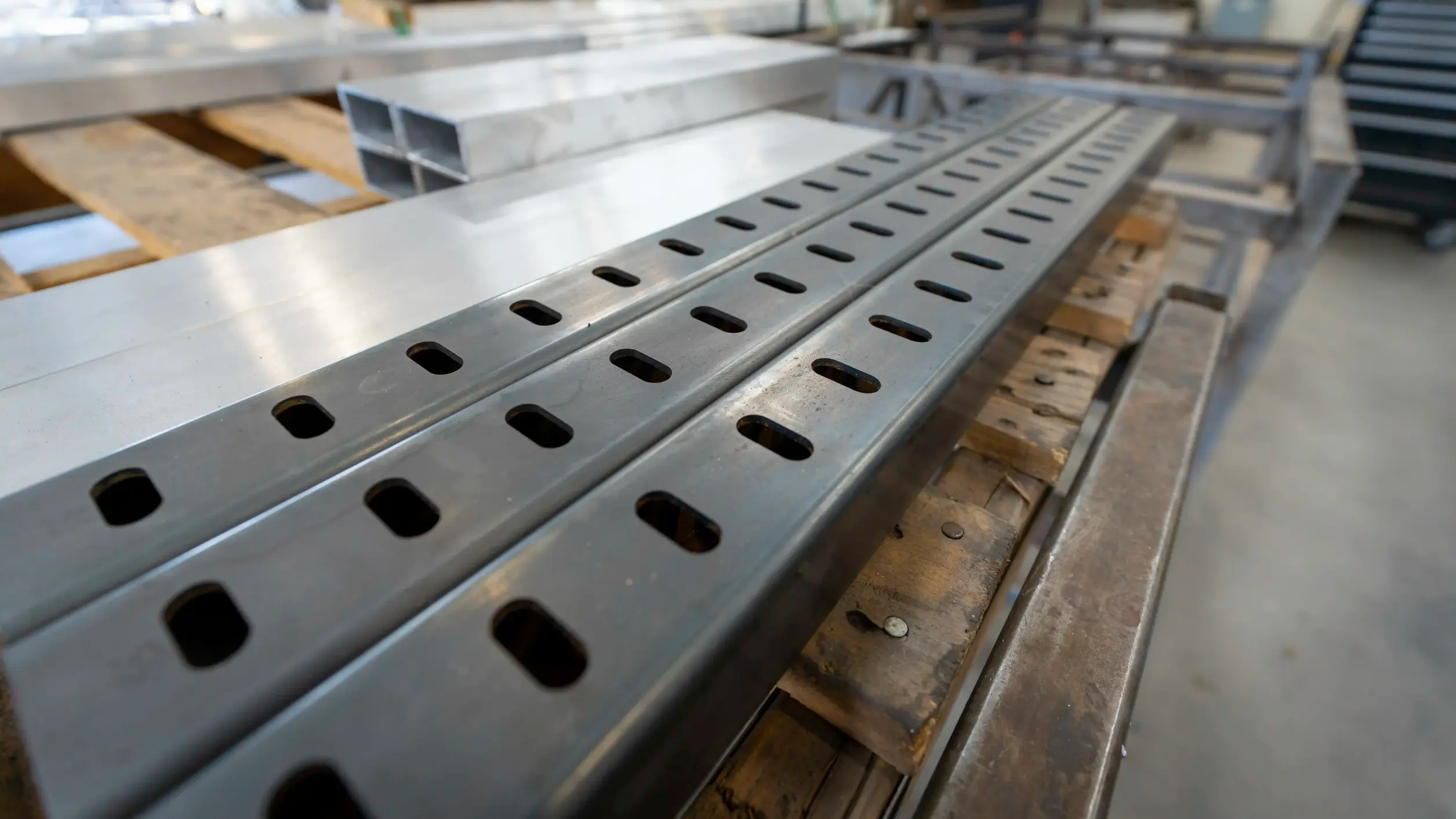
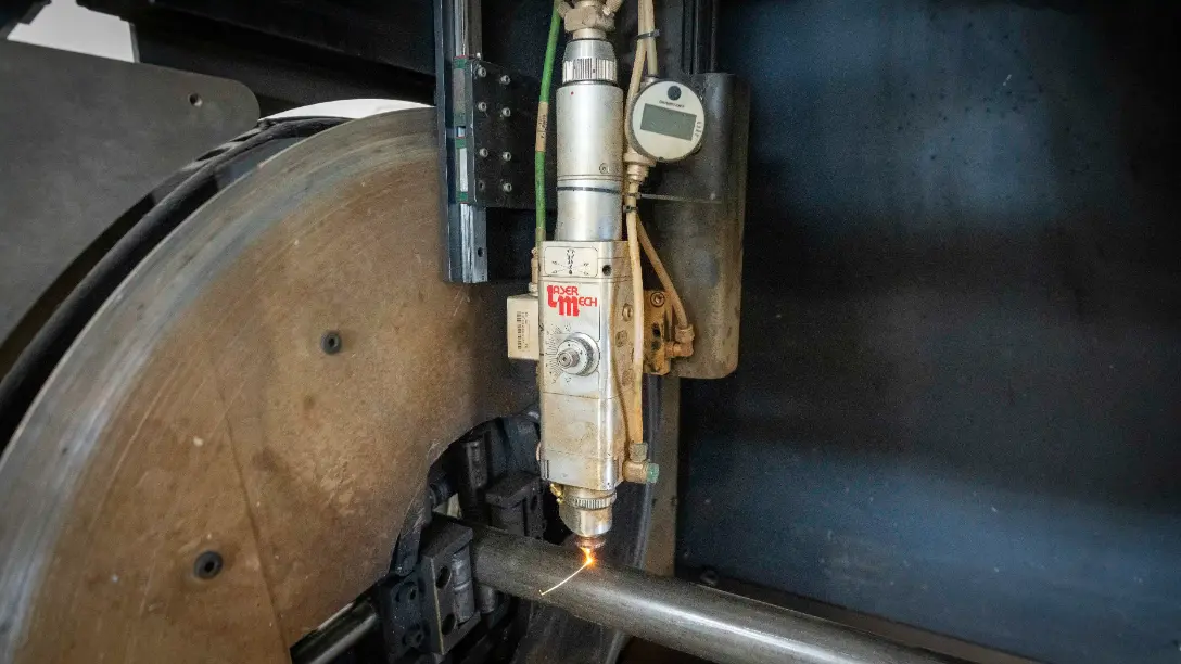
Be sure to check out the Learn page for a detailed guide on how to draw and submit CAD files for tube laser cutting. We accept .xt, IGES, and .STEP formats to ensure compatibility with our system. To avoid design issues, make sure your parts fit within our chuck size envelope of 8.5” x 8.5”. When designing, be sure to include appropriate radii on both the inside and outside edges of the tubing. If you're unsure, a good rule of thumb is to set the outer radius to 1.5 times the material thickness. Even for sharp-corner aluminum tubing, an outside radius of at least 0.02” is required to ensure proper cutting and fitment.
Tube Bending and Rolling
CNC tube bending and radius rolling are precise, automated processes driven directly from CAD files, ensuring accurate, repeatable results while reducing setup time and errors. We make manufacturing easy—just send us a CAD file in .XT, STEP, or IGES, and we’ll generate bend and roll instructions with minimal adjustments. Whether it’s tight-radius bends, large sweeping rolls, or complex clocked geometries, our CNC machines deliver high-quality precision. With a streamlined workflow, you get fast, reliable production that brings your designs to life effortlessly.
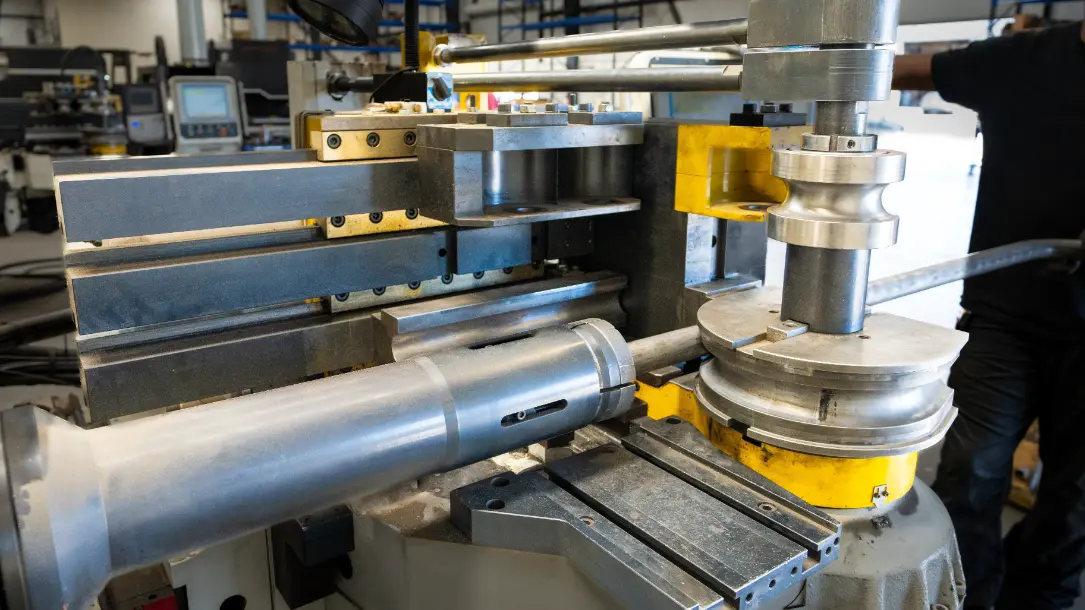
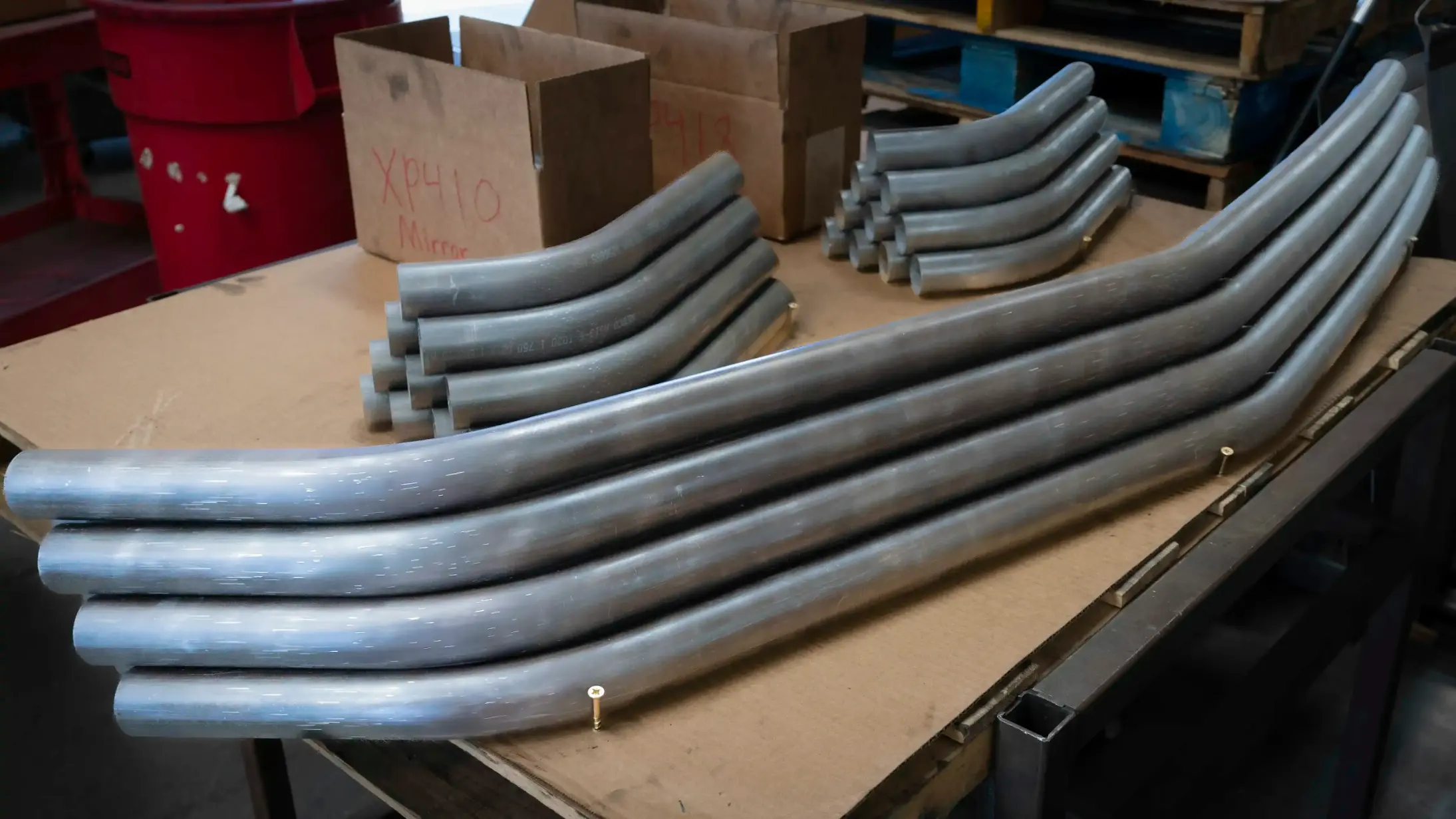
Check out our Learn page to understand CAD file preparation and modeling guidelines for your next tube project. Be sure to model using the exact tube radius sizes (CLR) charted on our Learn page to ensure your parts come out precisely as designed. A few important rules to follow: avoid cuts, features, or markings on any bend sections, allow for at least 4 inches between bends and rolls, and maintain a minimum of 3 inches of straight tube before and after a bend. Proper modeling helps streamline the bending process, reduces errors, and ensures a perfect fit for your project.
Plate Laser Cutting
Waterjet cutting available for thick materials!
Plate laser cutting ensures precise cuts for excellent fitment, making fabrication more efficient. It allows for detailed features, including holes, alignment keys, and custom shapes, reducing assembly time and improving accuracy. Unlike traditional methods like waterjetting and plasma cutting, which require extensive cleanup and take longer, laser cutting produces clean, smooth edges that are nearly ready to use, minimizing additional processing and ensuring a faster, more streamlined workflow.
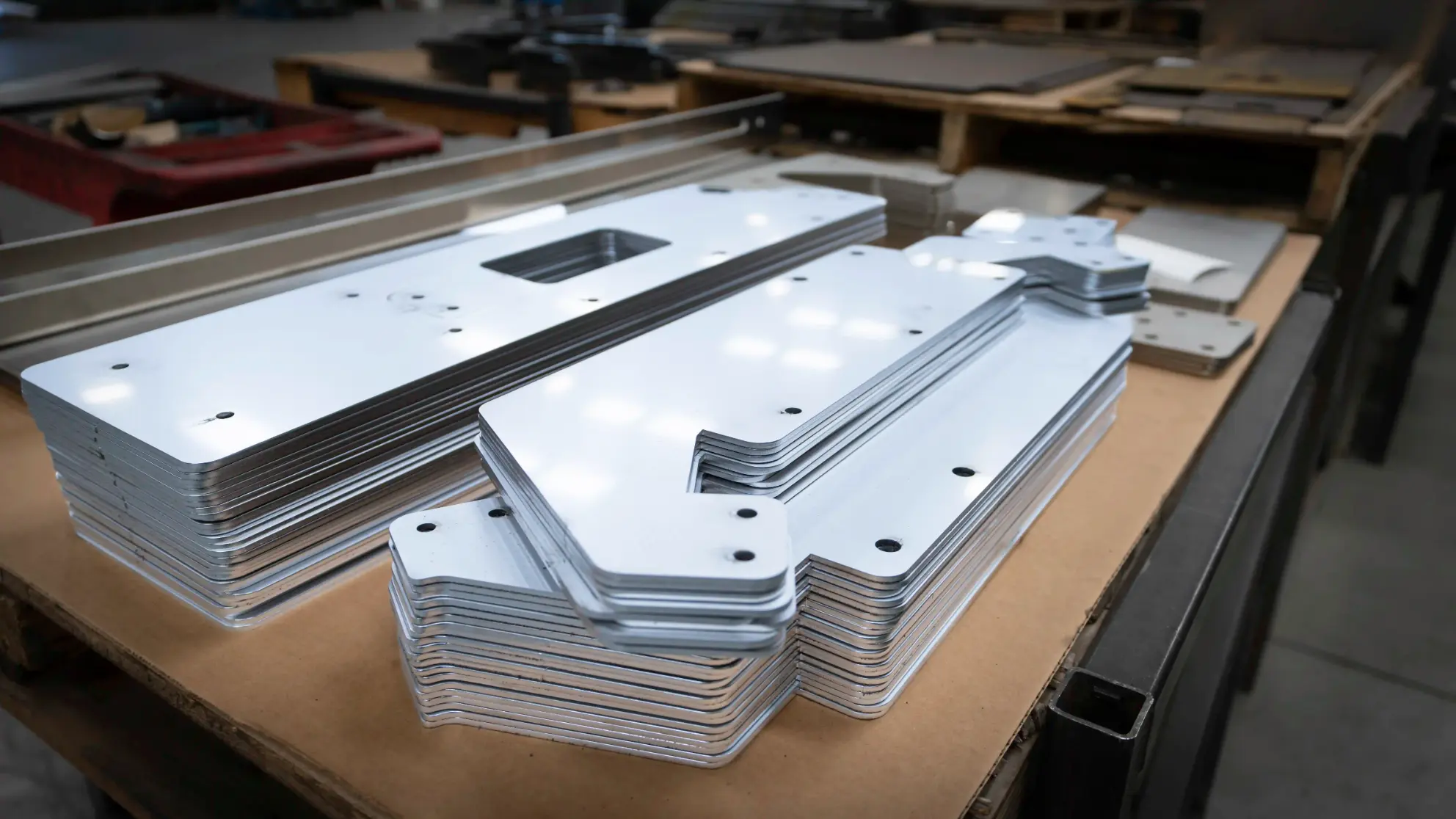
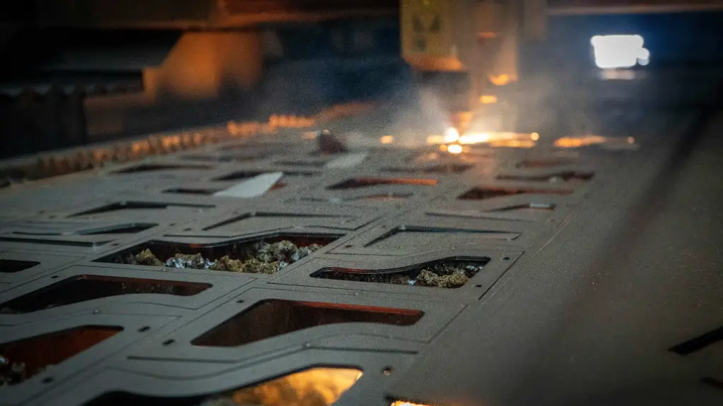
Check out our Learn page to ensure your files are properly prepared for submission. When designing, make sure holes and features aren’t too close to bends, as this can weaken the material or affect accuracy. Using the correct bend radius and k-factor is essential for precise results. While we can make some adjustments, it’s best when parts come in correctly. Be sure to call out all material requirements when submitting files to avoid delays and ensure the best possible outcome.
Bending plate after laser cutting is a common practice that ensures precision and repeatability. We use modern controls on our press brakes to automatically generate bend programs, guiding the operator on die placement and bending steps with minimal manual input. This advanced technology reduces human error and improves accuracy. Programs can be saved, allowing the process to be exactly repeated for future reorders. Our tooling is kept new and well-maintained, ensuring consistency over time.
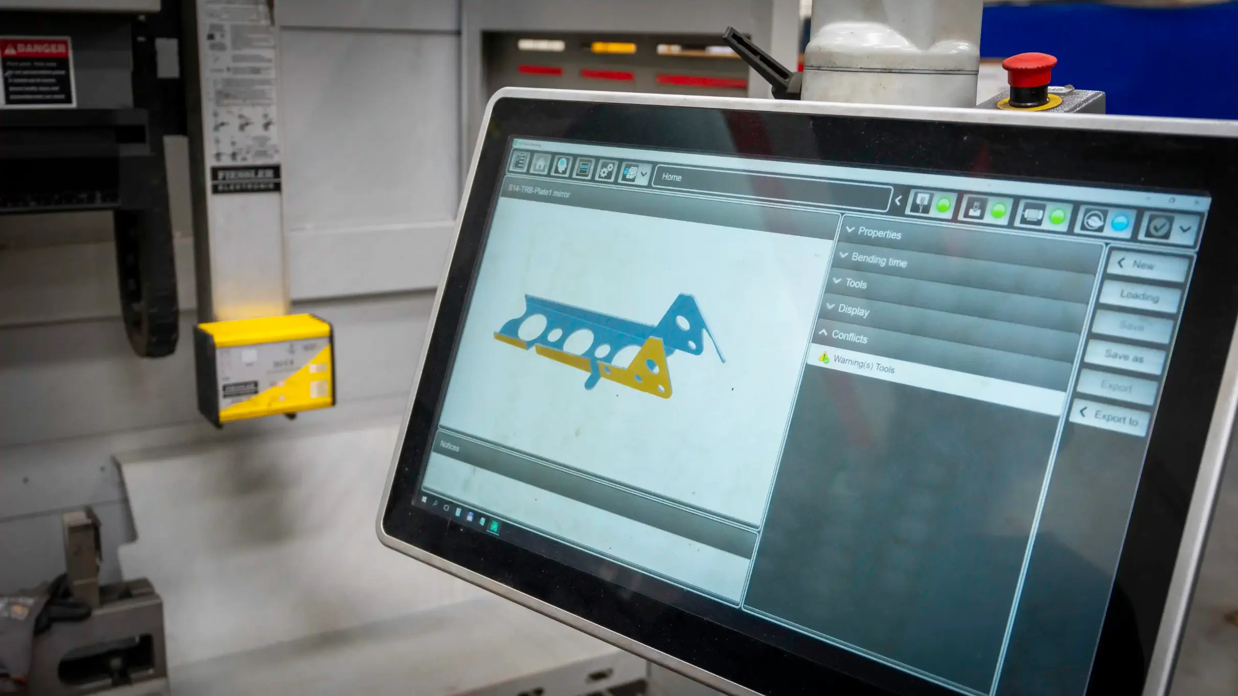
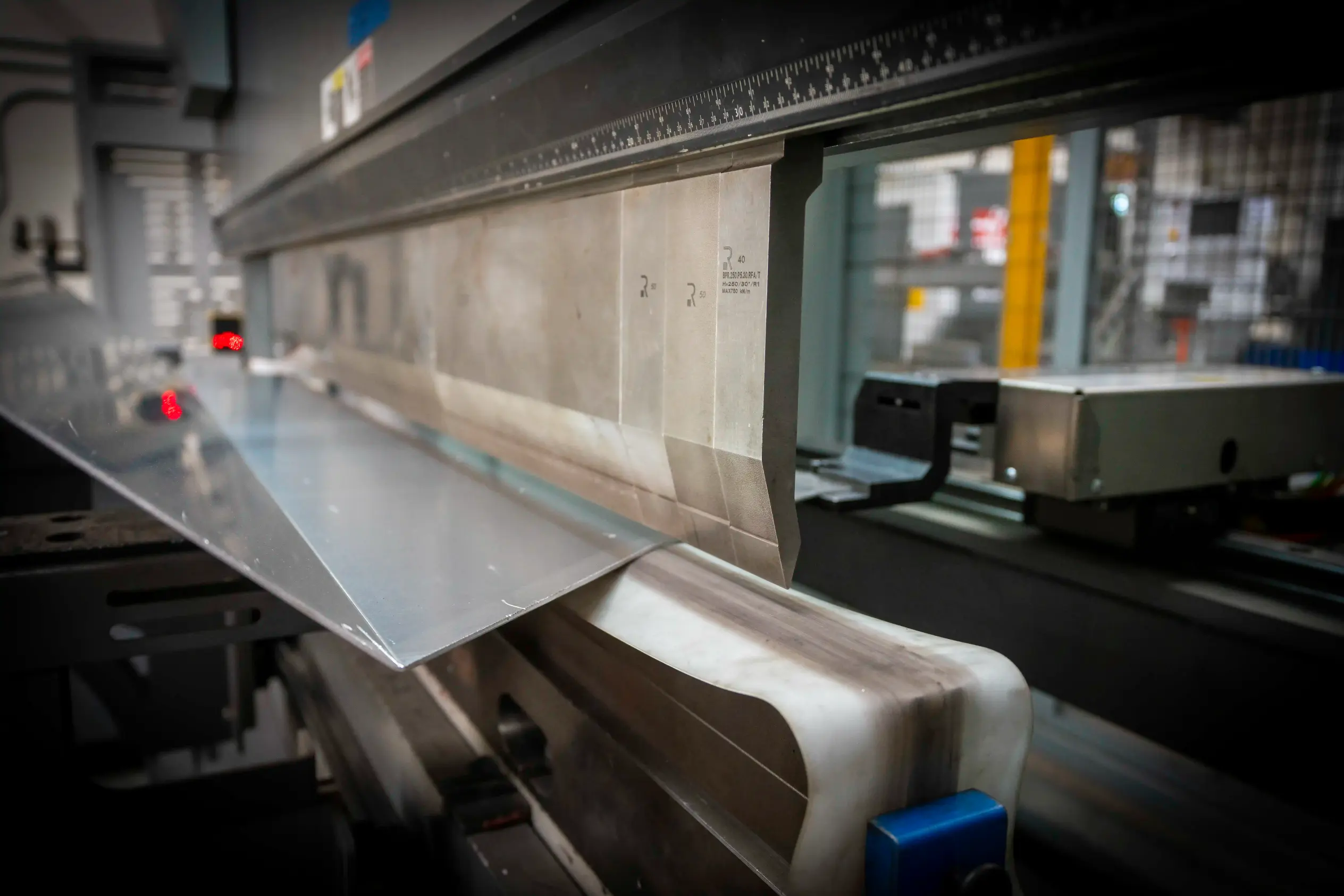
The best way to submit plate for bending is with a 3D CAD file in .xt, IGES, or STEP format, allowing our software to automatically unbend the design and create accurate DXF files. While drawings are encouraged, they are not always required, depending on the details provided at the time of order. The Material page lists common daily materials, but we can source others if needed. To ensure the most accurate part, follow the inner bend radius and K-factor chart.
Welding and Assembly
Having welding in the same building as the plate, tube, and machining departments creates a seamless manufacturing process, reducing lead times and ensuring precision. To guarantee a successful weld, all weld assemblies should be submitted with detailed drawings that clearly outline the necessary specifications. Important details such as weld callouts, material requirements, and any post-machining after welding must be included to ensure accuracy and efficiency in the final part.
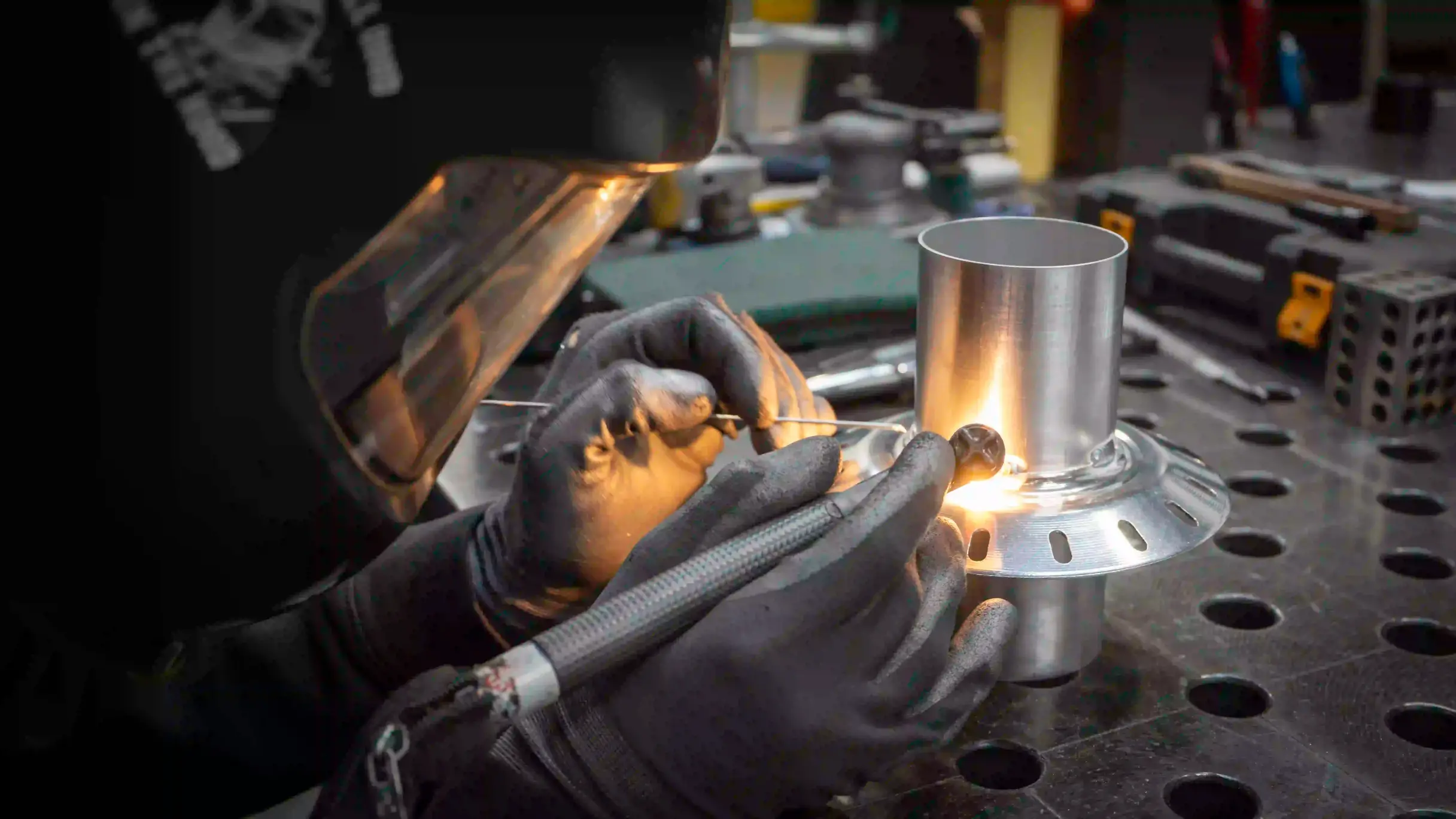
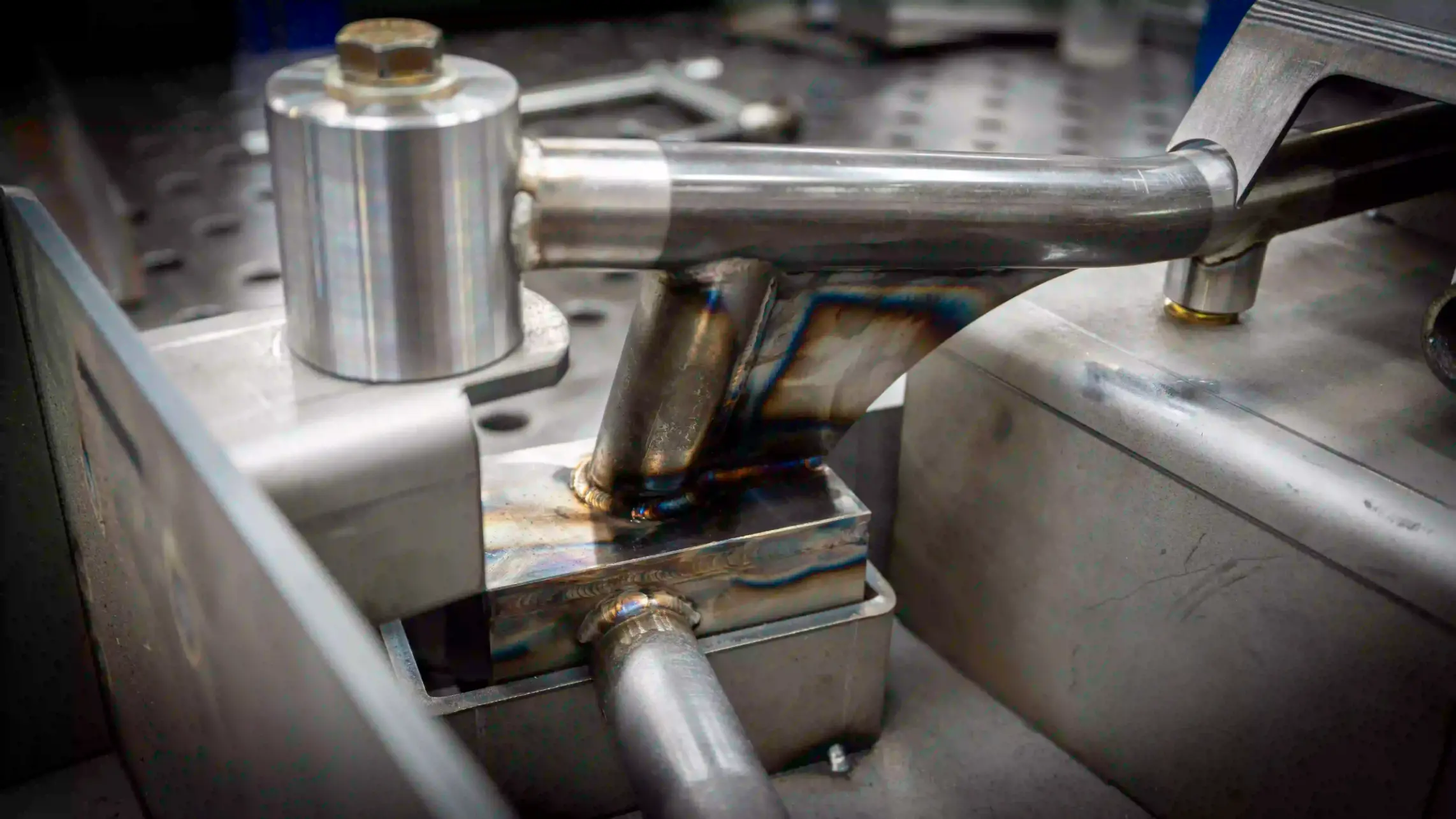
We can handle both large and small assemblies with precision and efficiency. Our precision-ground tables provide a stable and accurate foundation to ensure every welded part meets tight tolerances. For complex projects, in-house fixture design is available upon request, allowing for greater consistency and repeatability. Custom fixtures can improve both accuracy and production speed, ensuring high-quality results while streamlining the welding process.
Turning and Machining - 3, 4, and 5 Axis
Our Turning and Machining department is equipped with state-of-the-art dual-spindle lathes with bar feeders, allowing for efficient and precise production of complex parts. We utilize advanced 3, 4, and 5-axis machining capabilities to handle intricate geometries and high-precision components with minimal setups. To ensure top-tier quality, our department is supported by CMM (Coordinate Measuring Machine) inspection equipment, which enables us to generate detailed quality reports and maintain strict adherence to specifications. This combination of technology and expertise allows us to deliver high-accuracy, high-efficiency machining solutions for a wide range of applications.
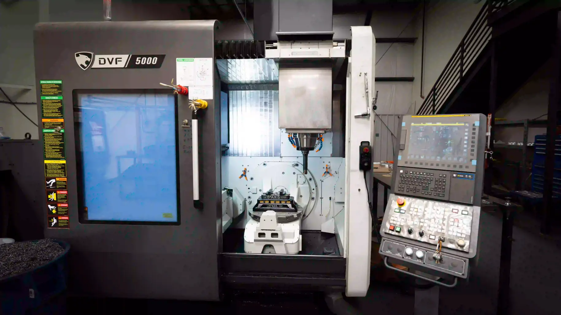
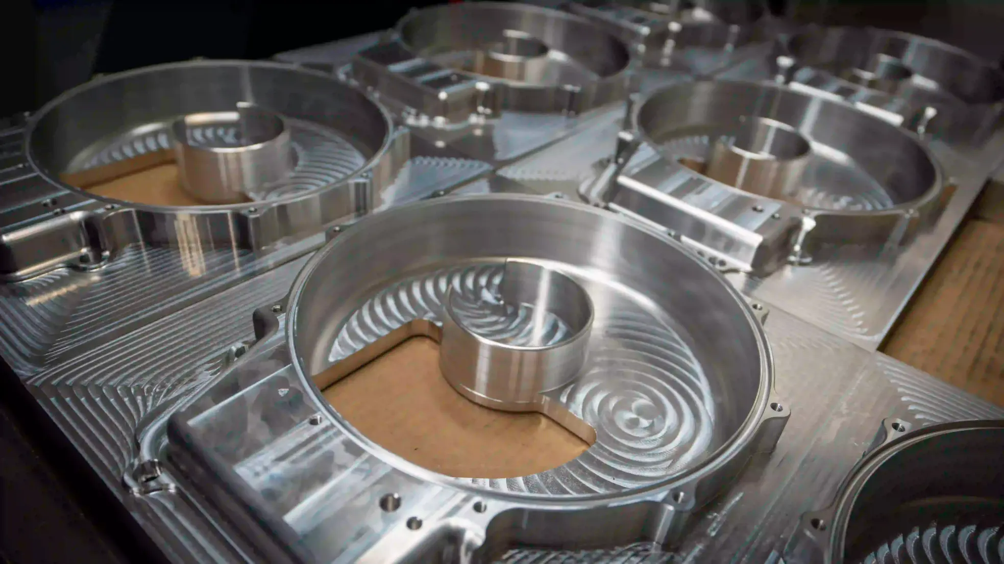
Clear and concise drawings are essential for efficient and accurate machining. Our team frequently reaches out to clarify any ambiguities in drawings to ensure that every detail is fully understood before production begins. Well-defined prints help prevent delays and costly errors while allowing us to optimize machining processes. Additionally, providing 3D models in .XT, IGES, or STEP format is crucial for programming our CNC machines and ensuring precision. Quantity also plays a significant role in overall unit cost, as higher volumes often allow for more efficient setups and reduced cycle times. Accurate drawings and clear communication help us deliver high-quality parts while maintaining cost-effective production.
Built to a published envelope.
Most shops make you ask. These are the limits the floor actually holds — design to them and the part comes off the machine matching your model.
8.5″
Tube OD capacity
24ft
Max tube length
188t
Press brake tonnage
5-axis
CNC machining
Common questions
Where is CalWest Manufacturing and what do you make?
CalWest Manufacturing is in Fontana, California. Tube laser cutting, CNC tube bending, plate laser cutting, press brake forming, welding, 5-axis machining and FANUC robotic integration all happen in one building.
What certifications does CalWest hold?
We are AS9100D and ISO 9001 certified and ITAR registered.
How do I get a quote?
Send a 3D model in Parasolid (.x_t), STEP or IGES through the request-a-quote page. Drawings are needed for welded assemblies and machined parts, with weld callouts, material and any post-weld machining called out.
What size parts can you make?
Tube up to 8.5 in OD and 24 ft long on the tube laser, and press brake forming on a 188-ton brake. Waterjet cutting is available for thick materials. Each service page lists the full limits.
Can you do cutting, bending, welding and machining on one job?
Yes. Cutting, forming, welding and machining are in the same building, so a part goes from CAD file to finished assembly without leaving it.